Control RGB LEDs ( Arduino Uno )
Arduino USB Control with Firmata Library
Arduino Firmata Library is source code to communicate or control Arduino Board with other device.
Firmata is already include in your Arduino IDE.
more info http://arduino.cc/en/reference/firmata

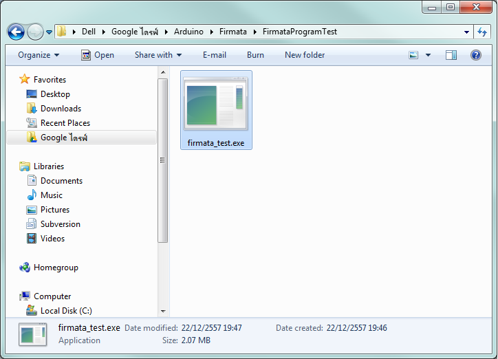
Firmata Test Program
This
"firmata_test" program works with boards running StandardFirmata version 2.2 or higher on standard Baud
rate 57600.
For Linux (32 bit)
For Linux (64 bit)
For Mac OS-X
For Windows
Source code

We Test on Windows ( see VDO above )
First Program Firmata Code to Arduino Board.
Open Arduino IDE ( we use Arduino 1.0.6 )


Then Upload to your Arduino Board
Open Firmata Test Program ( we test on Windows )


Firmata Command
Methods
Sending
Messages
Receiving
Messages
Callback Functions
Message
Types
My Website
http://softpowergroup.net/
email : info@softpowergroup.net Tel .081-6452400
Google+ https://plus.google.com/+SoftpowergroupNetThailand/
First Program Firmata Code to Arduino Board.
Open Arduino IDE ( we use Arduino 1.0.6 )
Goto File > Examples > Firmata > StandardFirmata
Then Upload to your Arduino Board
Open Firmata Test Program ( we test on Windows )
Connect USB to your Arduino Board then Select port.
Ready To Control
Android USB Control with Firmata
Firmata Command
Methods
begin()
start the library
begin(long)
start the library and
override the default baud rate
printVersion()
send the protocol
version to the host computer
blinkVersion()
blink the protocol
version on pin 13
printFirmwareVersion()
send the firmware name
and version to the host computer
setFirmwareVersion(byte
major, byte minor)
set the firmware name
and version, using the sketch's filename, minus the .pde
Sending
Messages
sendAnalog(byte
pin, int value)
send an analog message
sendDigitalPorts(byte
pin, byte firstPort, byte secondPort)
send digital ports as
individual bytes
sendDigitalPortPair(byte
pin, int value)
send digital ports as
one int
sendSysex(byte
command, byte bytec, byte* bytev)
send a command with an
arbitrary array of bytes
sendString(const
char* string)
send a string to the
host computer
sendString(byte
command, const char* string)
send a string to the
host computer using a custom command type
Receiving
Messages
available()
check to see if there
are any incoming messages in the buffer
processInput()
process incoming
messages from the buffer, sending the data to any registered callback functions
attach(byte
command, callbackFunction myFunction)
attach a function to an
incoming message type
detach(byte
command)
detach a function from
an incoming message type
Callback Functions
In order to attach your function to a message type, your
function must match the standard callback function. There are currently three
types of callback functions in Firmata: generic, string,
and sysex.
generic
void callbackFunction(byte pin, int value);
system_reset
void systemResetCallbackFunction(void);
string
void stringCallbackFunction(char *myString);
sysex
void sysexCallbackFunction(byte pin, byte
byteCount, byte *arrayPointer);
Message
Types
These are the various message types that you can attach
functions to.
ANALOG_MESSAGE
the analog value for a
single pin
DIGITAL_MESSAGE
8-bits of digital pin
data (one port)
REPORT_ANALOG
enable/disable the
reporting of analog pin
REPORT_DIGITAL
enable/disable the
reporting of a digital port
SET_PIN_MODE
change the pin mode
between
INPUT/OUTPUT/PWM/etc.FIRMATA_STRING
C-style strings, uses
stringCallbackFunction for the function typeSYSEX_START
generic, arbitrary
length messages (via MIDI SysEx protocol), uses
sysexCallbackFunction for the function typeSYSTEM_RESET
message to reset
firmware to its default state, uses
systemResetCallbackFunction for the function type
My Website
http://softpowergroup.net/
email : info@softpowergroup.net Tel .081-6452400
Google+ https://plus.google.com/+SoftpowergroupNetThailand/


