Monday, June 4, 2012

Android ADK Microcontroller Board

Android ADK Micro-controller Board

The Accessory Development Kit (ADK) is basically a micro-controller development board that adheres to the simple Open Accessory Standard Protocol created by Google as a reference implementation. Although that could be any board fulfilling the specification to be ADK compatible, most boards are based on the Arduino design, which is an open hardware platform created in 2005. Those boards are USB-enabled micro-controller boards based on the Arduino Mega2560 and the implementation of the Circuits@Home USB Host Shield. However, there are other board designs known to be ADK compatible, such as PIC-based boards or even plain USB host chip boards such as the VNCII by FTDI. Google decided to build its reference kit upon the Arduino Mega2560 design and provided the software and hardware resources as open source. This was a clever move because the Arduino community has grown tremendously over the last years, enabling designers, hobbyists, and average Joes to easily make their ideas come to life. With the ever-growing communities of both factions of Android and Arduino enthusiasts, the ADK had a pretty good start.

To communicate with the hardware boards, an Android-enabled device needs to fulfill certain criteria. With Android Honeycomb version 3.1 and backported version 2.3.4, the necessary software APIs were introduced. However, the devices also have to ship with a suitable USB driver. This driver enables general USB functionality but, in particular, it enables the so-called accessory mode. The accessory mode allows an Android device that has no USB host capabilities to communicate with external hardware, which in turn acts as the USB host part.
 
The specification of the Open Accessory Standard stipulates that the USB host has to provide power for the USB bus and can enumerate connected devices. The external device has to provide 500mA at 5V for charging purposes of the Android device according to the USB 2.0 specification.

The ADK also provides firmware for the development board which comes in the form of a set of source code files, libraries, and a demokit sketch, which is the Arduino term for a project or source code file. The firmware cares about the enumeration of the USB bus and finding a connected device that is accessory modecompatible.
Google also provides an example app for the Android device that easily accesses and demonstrates the capabilities of the reference board and its sensors and actuators. If you are working with a derivative board that doesnt have the same variety of sensors, you still can work with the example app, but you might want to strip the code down to only the basic part of the communication.
When you set up an ADK hardware project you are building a so-called Android accessory. Your hardware project is an accessory for the Android device such as, for example, a keyboard would be for a PC, with the difference being that your accessory provides the power for the whole system. Accessories need to support the already mentioned power supply for the device and they must adhere to the Android accessory protocol. The protocol dictates that the accessory follows four basic steps to establish a communication to the Android device:

1. The accessory is in wait state and tries to detect any connected devices.
2. The accessory checks for accessory mode support of the device.
3. The accessory tries to set the device in accessory mode if it is necessary.
4. If the device supports the Android accessory protocol, the accessory establishes the communication.
If you want to learn more about the ADK and the Open Accessory Standard have a look at the Android developer pages at http://developer.android.com/guide/topics/usb/adk.html.


The Google ADK Board
The Google ADK is the reference kit presented at the Google IO in May 2011 and it was the first board adhering to the Open Accessory Standard. The kit comes with the ADK base board and a demo shield, as shown in Picture.
The Arduino ADK Board
The Arduino ADK  is an ADK-compatible base board from the makers of the Arduino series themselves. It is also based on the ATmega2560 and only differs slightly from the Google reference board.


The Seeeduino ADK Board
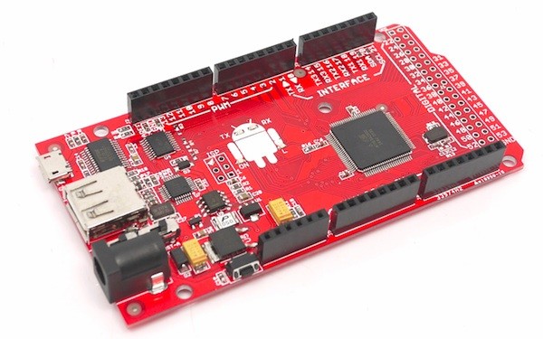
The Seeeduino ADK board (Figure 1-5), also derived from the ATmega board, looks quite similar to the standard Arduino ADK board but, at second glance, it has some nice extra features


The IOIO Board
The IOIO (pronounced yo-yo) board is a PIC micro-controllerbased development board developed by Sparkfun Electronics before the announcement of the Open Accessory Standard.


More ADK Possibilities
After you have seen the most common boards with ADK support out there, youll probably wonder if thats all there is. Although the Open Accessory Standard is only about a year old, the number of boards already available is incredible, with many still to come in this young but rapidly evolving field of open source hardware. There are still plenty of other possibilities for developing with the Open Accessory Standard. Some represent pure DIY (do-it-yourself) approaches, while others are extensions for boards that have been in use since before the ADK came out.
One early approach was to port the ADK to the common Arduino Uno or Duemilanove. The only thing you needed was an additional USB host shield to connect the Android device to. I was one of those early DIY hackers who went in that direction. At the time, it was the only affordable alternative to the original Google reference board. Nowadays, I wouldnt recommend it; there are already perfect all-inone boards that dont need additional shields, hacking, or stripping of code. If you still want to use your regular Arduino there are a lot of shops carrying USB host shields you can use:


Which Board Should You Use?
Now that you have read about the variety of boards supporting the Open Accessory Standard that are already out there you might wonder which board is the right one for your own project. This is always a hard question, for which there is no single answer. You should plan your project thoroughly ahead of time to analyze which board fits best.
If you are a beginner in the world of hardware development and ADK, you should stick to the boards that are most commonly used out in the wild. As of this writing, that would be the Google ADK board, which was given out to hundreds of developers attending the Google IO 2011. If you are not one of the lucky ones to have received one of these boards and your budget is pretty tightwhich is usually the caseconsider the standard Arduino ADK board. Both of these boards are used in most hacker and maker projects I have seen so far and they have a huge community built around them to help you if you are in need.

Table gives you an overview of the boards under discussion.

Comparison of the Most Common ADK-Enabled Boards

ADK Boards
Google ADK
Arduino ADK
Seeeduino ADK
Sparkfun IOIO

Processor
ATmega2560
ATmega2560
ATmega2560
PIC24FJ256

CPU clock speed
16 MHz
16 MHz
16 MHz
32 MHz
Flash memory
256 Kbytes
256 Kbytes
256 Kbytes
256 Kbytes
RAM
8 Kbytes
8 Kbytes
8 Kbytes
96 Kbytes
Digital IO pins
54 (14 PWM)
54 (14 PWM)
54 (14 PWM)
 48 (28 PWM)

Analog input pins
16
16
16
16
Input voltage
voltage 5.5V - 16V
voltage 5.5V - 16V
voltage 5.5V - 16V
5V - 15V
Connectors
DC power
USB A-type
USB micro B-type

DC power
USB A-type
USB B-type

DC power
USB A-type
USB micro B-type

USB A-type


More info
What is Android ADK? 

Beginning Android ADK with Arduino eBook. ( Free Download )

Thursday, May 24, 2012

One PIC Microcontroller Platform Development Board


One PIC Microcontroller Platform Development Board
 
Develop firmware using Microchip's 8/16/32-bit PIC® Microcontrollers all on one board!
Each device comes preprogrammed with firmware to operate the LCD, LED and capacitive touch pads. In addition to three PIC® Microcontrollers, this board also has a dedicated Real-Time Calendar Clock circuit and is able to run from a single AAA Ultimate Lithium battery.

Feature
PIC Microcontrollers
PIC16LF1939-I/PT
PIC24FJ256GA106-I/PT
PIC32MX795F512L-80I/PT
Capacitive Touch Pads
Segmented LCD

Colored LEDs
Single Cell Battery Supply
MCP1640T-I/CH
Real-Time Calendar Clock
1 MCP79410-I/S
PICkit™ 3 Connector
PICtail™ Board Connector

System Requirements:

Software:

·        MPLABX  V1.00
·        .NET Framework v2.0 or later (required for 8bit IR Demo GUI)
·        MCP2200 & SimpleIO-M.dll (required for 8bit IR Demo GUI)

Drivers:

·        MCP2200  (Downloaded)
·        ZENA Wireless Adapter (Provided)

Compilers ( use latest available versions):

·        PIC16 HI-TECH: (developed with v9.83)
·        PIC24 C30: (developed with v3.31)
·        PIC32 C32: (developed with v2.01)

Overview:

This demo board is populated with 8bit, 16bit, and 32bit PIC microcontrollers. Refer to the schematic of the board for more details.
8 bit MCU : PIC16LF1939
16 bit MCU: PIC24FJ256GA106
32 bit MCU: PIC32MX795F512L

OnePIC Demo Board

The demo code consists of:
1.     A “base” code which demonstrates the
a.      LCD
b.     LEDS
c.      mTouch
d.     Potentiometer
e.      Switch
2.     Three Wireless Demonstrations, one for each PIC
a.      8bit – Infrared
b.     16bit – RF4CE (Radio Frequency for Consumer Electronics)
c.      32bit – WiFi

The following document is intended as a walk-through guide to using the provided software.  Items will be presented in the order they might be presented during a demonstration of the OnePIC board.


Download Schematic

Thursday, February 16, 2012

Arduino control 8 devices via Android Bluetooth


Arduino control 8 devices via Android Bluetooth


Hardware สำหรับ การสร้างอุปกรณ์ภาครับ
  จะใช้ Bluetooth Module และ Arduino Microcontroller Board และ Relay Output Board
Hardware อุปกรณ์ที่ใช้

  •           Serial Port Bluetooth Module( TTL )
  •           Arduino Microcontroller Board (ET-BASEAVR EASY328 ) Arduino Compatible Board
  •           8 channel Output Relay Board


Wiring Diagram การต่อสายใช้งาน

Output 1 to Pin 4 ( Arduino Board )
Output 2 to Pin 5
Output 3 to Pin 6
Output 4 to Pin 7
Output 5 to Pin 8
Output 6 to Pin 9
Output 7 to Pin 10
Output 8 to Pin 11

Bluetooth Module Tx to  Pin 0

Bluetooth Module Rx to  Pin 1

For Arduino Board


For ET-BASEAVR EASY328


Download Micro controller firmware


For Arduino Microcontroller Board Source code

#define LED_PIN1  4
#define LED_PIN2  5
#define LED_PIN3  6
#define LED_PIN4  7

#define LED_PIN5  8
#define LED_PIN6  9
#define LED_PIN7  10
#define LED_PIN8  11

int firstSensor = 0;         // first analog sensor
int secondSensor = 0;    // second analog sensor
int thirdSensor = 0;        // digital sensor
int inByte = 0;               // incoming serial byte
boolean status_unlock;
boolean status_bluetooth;

long interval = 1000;           // interval at which to blink (milliseconds)
long previousMillis = 0;        // will store last time LED was update
int minite,sec;


void setup()
{
  // start serial port at 9600 bps:
  Serial.begin(9600);
  //pinMode(2, INPUT);   // digital sensor is on digital pin 2
  //establishContact();    // send a byte to establish contact until receiver responds
 
  pinMode(LED_PIN1, OUTPUT);
  pinMode(LED_PIN2, OUTPUT);
  pinMode(LED_PIN3, OUTPUT);
  pinMode(LED_PIN4, OUTPUT);

  pinMode(LED_PIN5, OUTPUT);
  pinMode(LED_PIN6, OUTPUT);
  pinMode(LED_PIN7, OUTPUT);
  pinMode(LED_PIN8, OUTPUT);
 
  digitalWrite(LED_PIN1, LOW);  // switch off LED
  digitalWrite(LED_PIN2, LOW);  // switch off LED
  digitalWrite(LED_PIN3, LOW);  // switch off LED
  digitalWrite(LED_PIN4, LOW);  // switch off LED
   
  digitalWrite(LED_PIN5, LOW);  // switch off LED
  digitalWrite(LED_PIN6, LOW);  // switch off LED
  digitalWrite(LED_PIN7, LOW);  // switch off LED
  digitalWrite(LED_PIN8, LOW);  // switch off LED
 
  status_bluetooth = true;
  status_unlock = false;
  sec = 0;
}

void loop()
{
  if (Serial.available() > 0) {  
      
    inByte = Serial.read();                      // get incoming byte: 

    if(inByte == 'A'){   
      digitalWrite(LED_PIN1, HIGH);        // switch on LED
      Serial.print('A', BYTE);                    // send a char
      //delay(800);
      digitalWrite(LED_PIN1, LOW);        // switch off LED
      status_unlock = false;
      inByte = 0;    
    }
   
    if(inByte == 'a'){   
      digitalWrite(LED_PIN2, HIGH);        // switch on LED
      Serial.print('a', BYTE);                    // send a char
      //delay(800);
      digitalWrite(LED_PIN2, LOW);        // switch off LED
     
      status_unlock = true;
      sec = 0;
      inByte = 0;    
    }
   
    if(inByte == 'B'){   
      digitalWrite(LED_PIN3, HIGH);        // switch on LED
      Serial.print('B', BYTE);                    // send a char
      inByte = 0;    
    }
   
    if(inByte == 'b'){   
      digitalWrite(LED_PIN3, LOW);        // switch off LED
      Serial.print('b', BYTE);                   // send a char
      inByte = 0;    
    }
   
    if(inByte == 'C'){   
      digitalWrite(LED_PIN4, HIGH);        // switch on LED
      Serial.print('C', BYTE);                    // send a char
      inByte = 0;    
    }
   
    if(inByte == 'c'){   
      digitalWrite(LED_PIN4, LOW);        // switch off LED
      Serial.print('c', BYTE);                    // send a char
      inByte = 0;    
    }
   
    if(inByte == 'D'){   
      digitalWrite(LED_PIN5, HIGH);        // switch on LED
      Serial.print('D', BYTE);                    // send a char
      inByte = 0;    
    }
   
    if(inByte == 'd'){   
      digitalWrite(LED_PIN5, LOW);        // switch off LED
      Serial.print('d', BYTE);                   // send a char
      inByte = 0;    
    }
   
    if(inByte == 'E'){   
      digitalWrite(LED_PIN6, HIGH);        // switch on LED
      Serial.print('E', BYTE);                    // send a char
      inByte = 0;    
    }
   
    if(inByte == 'e'){   
      digitalWrite(LED_PIN6, LOW);        // switch off LED
      Serial.print('e', BYTE);                   // send a char
      inByte = 0;    
    }
   
    if(inByte == 'F'){   
      digitalWrite(LED_PIN7, HIGH);        // switch on LED
      Serial.print('F', BYTE);                    // send a char
      inByte = 0;    
    }
   
    if(inByte == 'f'){   
      digitalWrite(LED_PIN7, LOW);        // switch off LED
      Serial.print('f', BYTE);                    // send a char
      inByte = 0;    
    }
   
    if(inByte == 'G'){   
      digitalWrite(LED_PIN8, HIGH);        // switch on LED
      Serial.print('G', BYTE);                    // send a char
      inByte = 0;    
    }
   
    if(inByte == 'g'){   
      digitalWrite(LED_PIN8, LOW);        // switch off LED
      Serial.print('g', BYTE);                   // send a char
      inByte = 0;    
    }   
   
    if(inByte == 'S'){   
     
      Serial.print('S', BYTE);                  // send a char
      status_bluetooth = true;
      sec = 0;
         
    }   
  } // if(Serial
 
  /*
  unsigned long currentMillis = millis();
     
              if(currentMillis - previousMillis > interval) {           
                previousMillis = currentMillis;         // save the last time you blinked the LED
               
                sec++;
               
                if(status_unlock==true){
               
                  if(sec== 11){
               
                      digitalWrite(LED_PIN1, HIGH);        // switch on LED
               
                      delay(800);
                      digitalWrite(LED_PIN1, LOW);        // switch off LED
               
                      status_unlock = false;                 
                      sec = 0;
                  }
                }
                else sec = 0;               
               
              }
 
 */
   
} //Loop

void establishContact() {
  while (Serial.available() <= 0) {
    Serial.print('.', BYTE);                   // send a capital A
    delay(500);
  }
}


Android Bluetooth Control Device

 
Android Bluetooth Control Device Application is to allow you to control various electrical devices up to eight devices and independently controlled.
Use Android Bluetooth mobile device to  remote control your device with Bluetooth Receiver hardware Device.
เป็น Application ที่ทำให้คุณสามารถควบคุมอุปกรณ์ไฟฟ้าต่างๆได้ ถึง 8 อุปกรณ์โดย แยกควบคุมกันได้อย่างอิสระ
ผ่านระบบ Bluetooth ของเครื่องโทรศัพท์มือถือ Android เป็นตัว Remote Control ไปยังอุปกรณ์ภาครับ ( Bluetooth Receiver Hardware Device )

The program features.
- control up to  8 devices.
- Can be set Timer to ON / OFF the device and show the time.(the timer can be set to 1 minute, 15 minutes, 30 minutes, 1 hour, 2 hours, 4 hours).
- Use with Receiving device (Bluetooth Receiver Hardware Device see below).
Design for the Android version 4 and a screen resolution of 480 x 800 (WVGA).
Freeware with AD (free software)


คุณสมบัติโปรแกรม
-          ควบคุมอุปกรณ์ได้ 8 อุปกรณ์
-          สามารถตั้งเวลา ปิด/เปิด แต่ละอุปกรณ์ได้ และแสดงเวลาการทำงาน และเวลาคงเหลือการตั้งเวลา 
(  เวลาที่สามารถตั้งได้ 1 นาที,15 นาที, 30 นาที, 1 ชั่วโมง ,2 ชั่วโมง , 4 ชั่วโมง ) 
-          ต้องใช้งานร่วมกับ อุปกรณ์ภาครับ ( Bluetooth Receiver Box )
ออกแบบ ค่าเริ่มต้น สำหรับ Android version 4 และ หน้าจอความละเอียด 480 x 800 ( WVGA )

A data transmission via Bluetooth. รูปแบบการส่งข้อมูลผ่าน Bluetooth
Device1 ON sent “A” , Device1 OFF sent “a”
Device2 ON sent “B” , Device2 OFF sent “b”
Device3 ON sent “C” , Device3 OFF sent “c”
Device4 ON sent “D” , Device4 OFF sent “d”
Device5 ON sent “E” , Device5 OFF sent “e”
Device6 ON sent “F” , Device6 OFF sent “f”
Device7 ON sent “G” , Device7 OFF sent “g”
Device8 ON sent “H” , Device8 OFF sent “h”


Wednesday, January 18, 2012

Arduino Microcontroller control Electromagnetic Door Lock


Arduino Microcontroller control Electromagnetic Door Lock with VB6

Microcontroller Board


Technical Data
  • Microcontroller: ATMega328
  • Main Crystal: 19.66MHz
  • Speed: up to 16 MIPS
  • Processor Language: AVR
  • High Level Language: Arduino (C++) (Bootloader Installed)
 By ETT      Model ET-BASE AVR Easy328


Relay Control Board. 


Electromagnetic Door Lock ( Electric Bolt )


RS-232 9 Pin Cable ( Come from with Microcontroller Board )

USB to RS-232 Convertor ( if your PC or Notebook not have RS-232 Port )


Diagram


VB code

Micro controller code

Thursday, November 24, 2011

Arduino Microcontroller control TCP/IP LAN Internet.


Arduino Microcontroller Board control device( LED ) via TCP/IP LAN Internet.
Now,we can make to control in 8 ch.


 Add Login to WebServer 


Arduino Microcontroller Board control device( LED ) via TCP/IP LAN Internet.

This project for test Arduino Microcontroller (ET-Base AVR Easy328 ) with TCP/IP Interface Board ( ET-MINI ENC28J60 ) to control device via TCP/IP, LAN and Internet.


In this VDO, present in Thai language.


Source code in C form http://www.nuelectronics.com